|
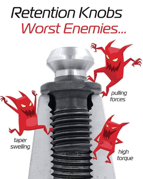
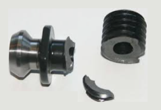
by Bernard Martin Retention Knobs are the critical connection between your machine tool and the tool holder and they are the only thing holding a steep taper tool holder in the machine’s spindle.
However, if you're running multiple shifts, 24-7, making lots of tool changes, making very heavy cuts with long reach or heavy cutting tools, and/or have ball lock style grippers instead of collet type grippers used on the retention knob, you will probably need to replace your studs at least every six months. Given the spindle speeds that we are running at to remain competitive, retention knobs are not an item that you want to take a chance on breaking. I can tell you firsthand that 5 pound toolholder with a drill in it flying out of the spindle at 23,000 RPM is not something you want to experience. Metal Fatigue: Why Pull Studs Fail
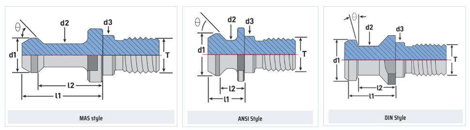
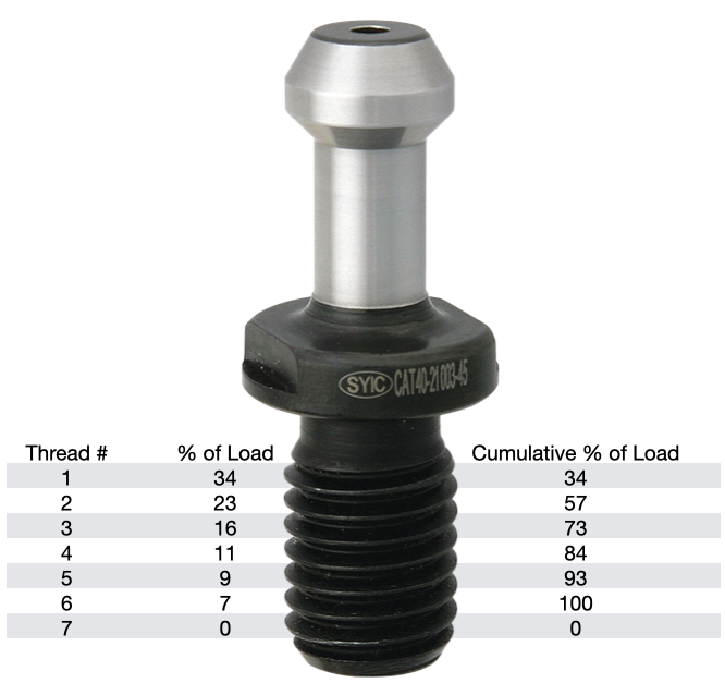
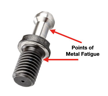
Additional threads beyond the sixth thread will not further distribute the load and will not make the connection any stronger. That is why the length of engagement of the thread on a pull stud is generally limited to approximately one to one & a half nominal diameter. After that, there is no appreciable increase in strength. Once the applied load has exceeded the first thread's capacity, it will fail and subsequently cause the remaining threads to fail in succession. Retention Knob DesignRepetitive cycles of loading and unloading subject the retention knob to stress that can cause fatigue and cracking at weak areas of the pull stud.
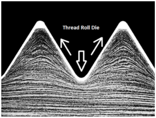
 Styles of MegaForce Retention Knobs MaterialNot all retention knobs are made from the same material, however, material alone does not make for a superior retention knob. Careful attention to design and manufacturing methods must be followed to avoid introducing potential areas of failure. Techniks MegaFORCE retention knobs are made from 8620H. AISI 8620 is a hardenable chromium, molybdenum, nickel low alloy steel often used for carburizing to develop a case-hardened part. This case-hardening will result in good wear characteristics. 8620 has high hardenability, no tempering brittleness, good weldability, little tendency to form a cold crack, good maintainability, and cold strain plasticity. There are some companies making retention knobs from 9310. The main difference is the lower carbon content in the 9310. 9310 has a tad more Chromium, while 8620 has a tad more nickel. Ultimate Tensile Strength (UTS) is the force at which a material will break. The UTS of 8620H is 650 Mpa (megapascals: a measure of force). The UTS of 9310H is 820 Mpa. So, 9310H does have a UTS that is 26% greater than 8620H. That said, Techniks chose 8620 as their material of choice because of the higher nickel content. Nickel tends to work harden more readily and age harden over time which brings the core hardness higher as the pull stud gets older. The work hardening property of 8620 makes it ideally suited for cold forming of threads on the MegaFORCE retention knobs. It should be noted that some companies are using H13. H13 shares 93% of their average alloy composition in common with 9310. 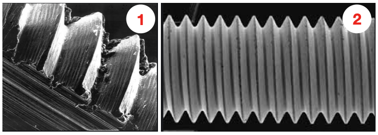 A cut thread, image 1, has a higher coefficient of friction due the the cutting process, while a roll formed thread, image 2, has a lower coefficient of friction which means that it engages deeper into the toolholder bore when subjected to the same torque. You will notice that Cutting threads tears at the material and creates small fractures that become points of weakness that can lead to failure. Rolled threads have burnished roots and crests that are smooth and absent of the fractures common in cut threads. Rolled Threads vs. Cut ThreadsRolled threads produce a radiused root and crest of the thread and exhibit between a 40% and 300% increase in tensile strength over a cut thread. The Techniks MegaFORCE retention knobs feature rolled threads that improve the strength of the knob by 40%.
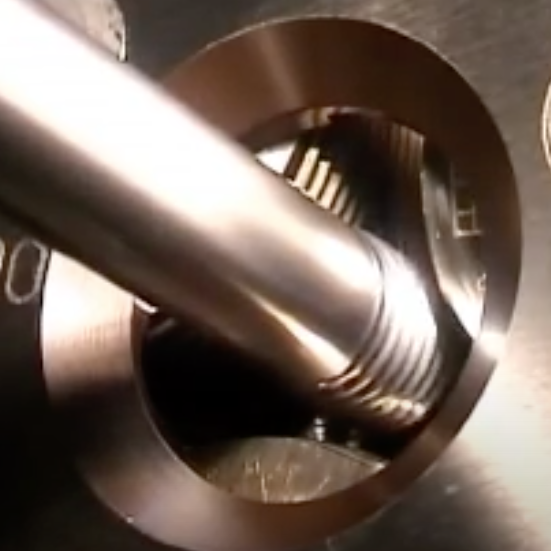
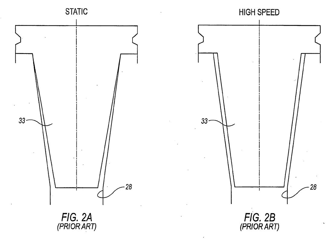
MegaFORCE Geometric Design Features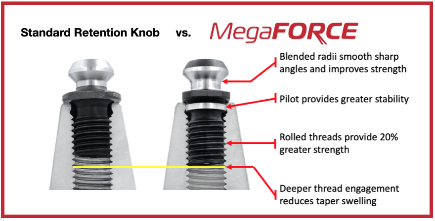 Features of Techniks MegaFORCE Retention Knobs Overall Length There are some claims that a longer projection engages threads deeper in the tool holder preventing taper swelling. While a deeper thread engagement can help prevent taper swelling, applying proper torque to the retention knob is an effective way to reduce taper swelling. An over-tightened retention knob may still cause taper swelling regardless of how deep it engages the threads of the tool holder. Additionally, the longer undercut section above the threads presents a weak point in the retention knob.
Retention Knob Best PracticesIn order to maximize the life of your retention knob and prevent catastrophic failure here are some technical tips to keep your shop productive and safe.
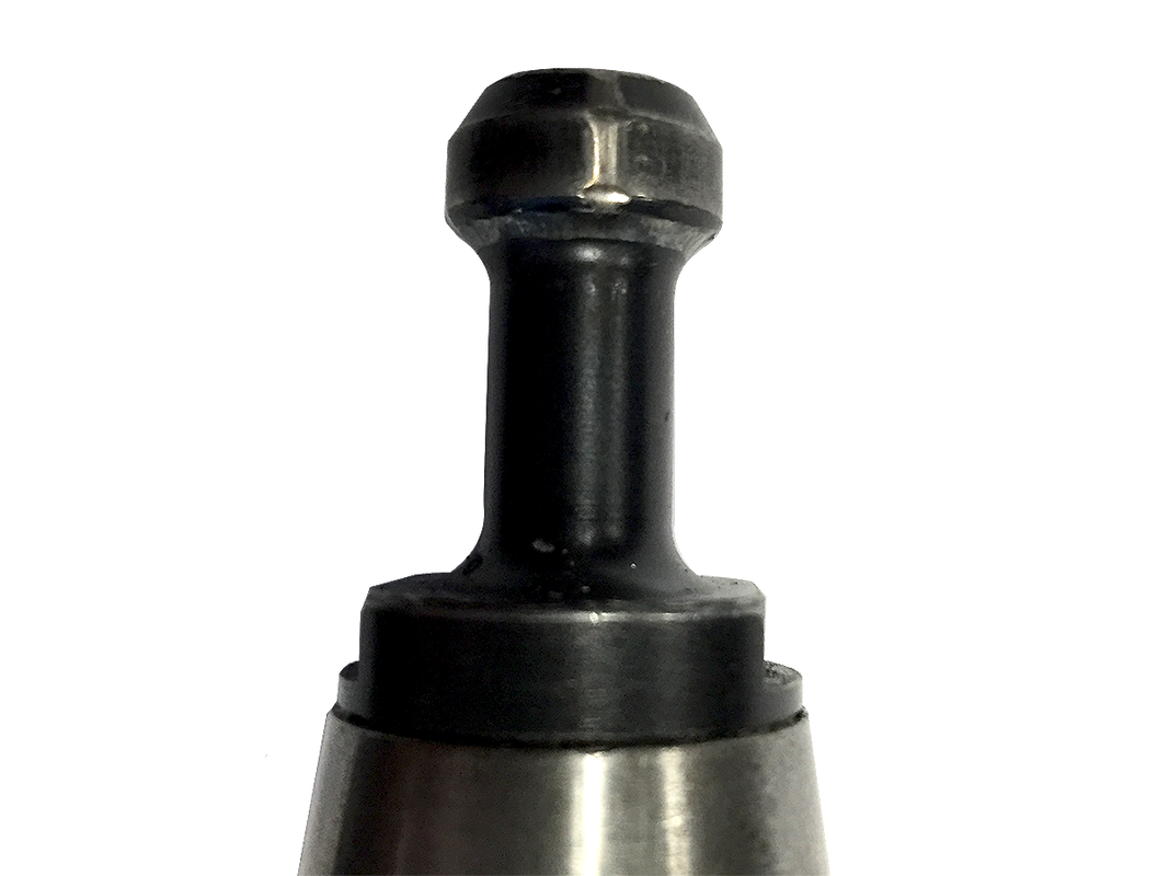
Indication Marks on Pull Studs is NOT Normal
Special thanks for Greg Webb at Techniks and Mike Roden from Fette Tools/ Turning Concepts, for providing technical insights.
0 Comments
General Overview Modern CNC machines feature high-capacity tool changers that automatically swap toolholders in and out of the spindle as needed, by means of a high speed swing arm or a rotary carousel.
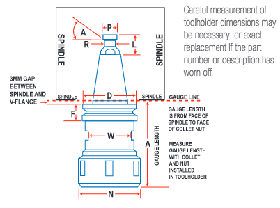
Sizing Toolholders
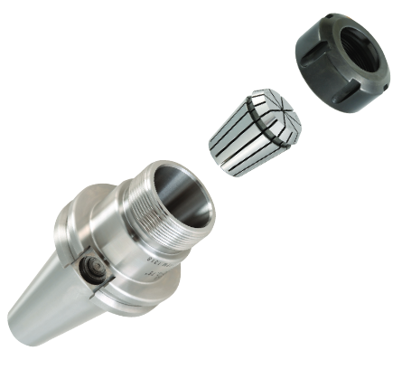
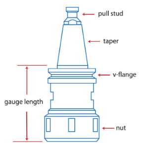
Parts of Toolholder
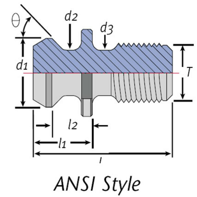
Pull Studs / Retention Knob
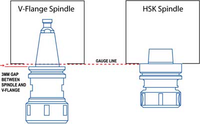
Taper
V- Flange
Collet Pocket  The last part of the toolholder is the collet pocket, into which the collet is inserted before being secured by various types of collet nuts. The collet pocket, internal 8 degree taper, should hold the same tolerance as the taper as they work together to control runout
Watch this video and learn how to check runout (total indicator runout or T.I.R.) to check your CNC machine tool holders performance. Good T.I.R. (less than .0002") keeps cutting tools cutting smoothly and prevents cutting tools from wearing out prematurely. Tool holders do wear out over time and if good T.I.R. cannot be achieved either the collet, nut, or holder may need replaced |
News & Applications
Learn about the latest breaking news and applications that we're working on right here! Archives
June 2022
Categories
All
|

 RSS Feed