General Overview Modern CNC machines feature high-capacity tool changers that automatically swap toolholders in and out of the spindle as needed, by means of a high speed swing arm or a rotary carousel.
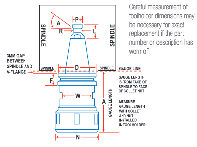
Sizing Toolholders
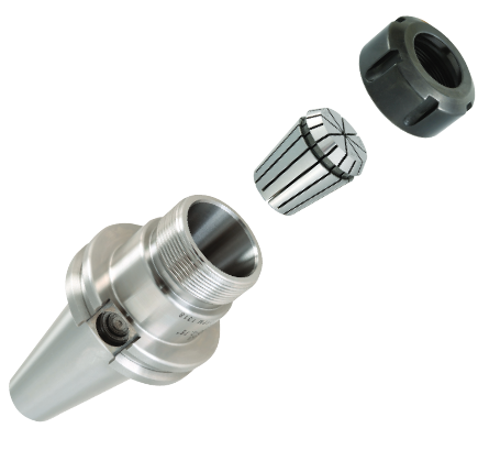
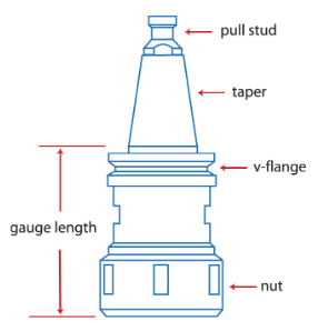
Parts of Toolholder
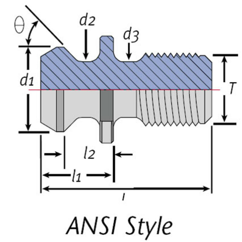
Pull Studs / Retention Knob
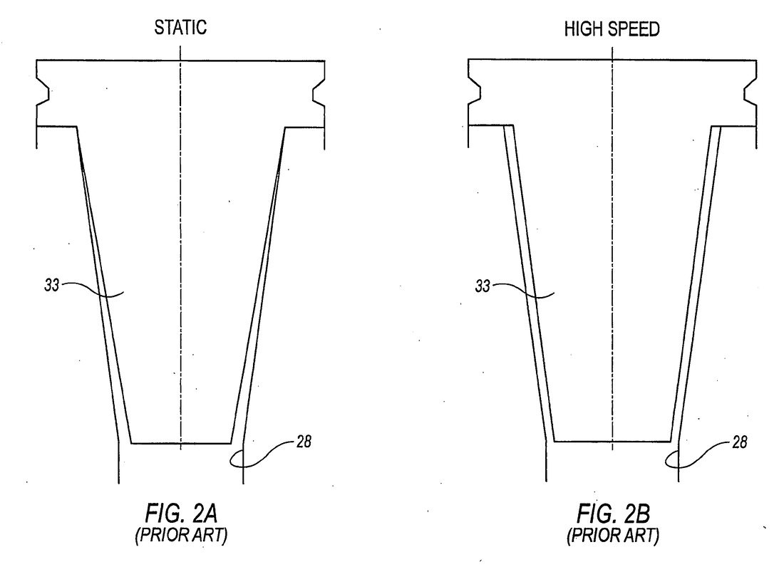
Taper
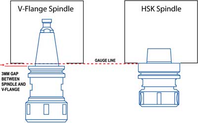
V- Flange
Collet Pocket 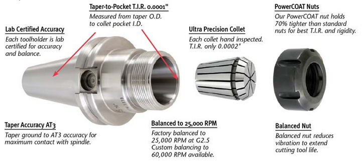 The last part of the toolholder is the collet pocket, into which the collet is inserted before being secured by various types of collet nuts. The collet pocket, internal 8 degree taper, should hold the same tolerance as the taper as they work together to control runout
0 Comments
Your comment will be posted after it is approved.
Leave a Reply. |
News & Applications
Learn about the latest breaking news and applications that we're working on right here! Archives
June 2022
Categories
All
|
 RSS Feed