|
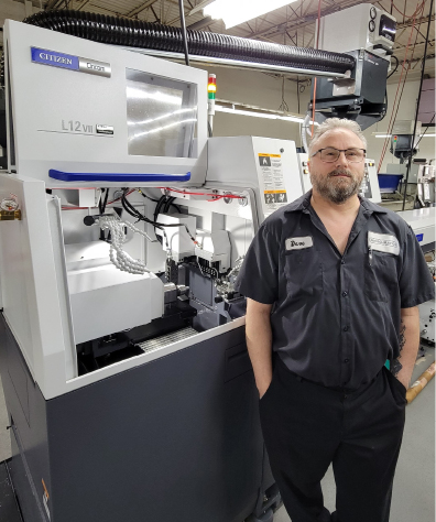
To avoid crushing and ruining parts, Swiss precision manufacturer Micro-Matics turned to Masa Tool’s Microconic collet and cartridge system. by Bernard Martin & Elizabeth Engler Modic, Today's Medical Developments May 2022 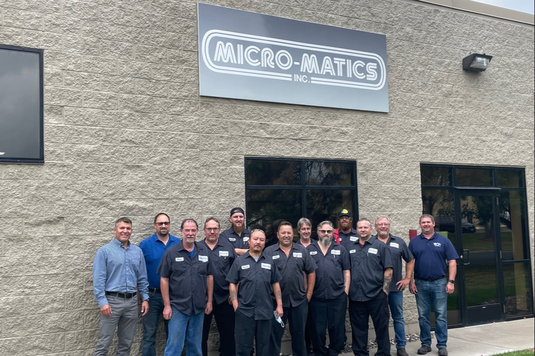 Micro-Matics employees outside the facility. All photos courtesy of Micro-Matics Since 1973, Micro-Matics of Fridley, MN, has been manufacturing CNC Swiss precision screw machine products including many kinds of contacts & pins, ground shafts, hardened bushings, rivets, screws, spacers and other custom parts for the medical, dental, aerospace, commercial, defense, computer, telecommunications and automotive industries. According to Jason Wobig, Operations Manager, "Micro-Matics is primarily an aerospace and medical components, Swiss machining job shop. We make components that are thousandths of an inch up to an 1-1/4" in diameter. We started out with the old manual style, Cam driven Swiss machines and we're one of the largest Escomatic shops in the Midwest. And as the company's grown and evolved, we've turned into Swiss job shop, mostly Citizen machines like the M16, a L12, and a M32, as well as a few Star and Tsugami machines that give us a wide variety of capabilities." Medical part challenges
High Tech Industrial Representation, Inc, or "High Tech" is a manufacturer's representative agency managing the territories of Minnesota, North Dakota and South Dakota, as well as Iowa & Nebraska. They represent industrial manufacturers whose products are focused on the machining industry and provide a high level of technical sales support. Todd brought in Masa's F20M10 Cartidge and the specific off-the-shelf Micorconic collet for the catheter part.
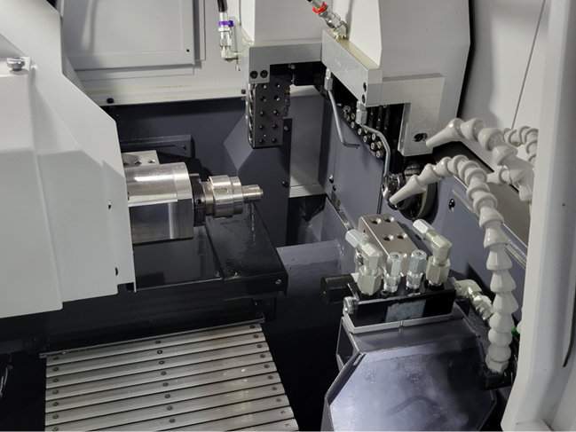
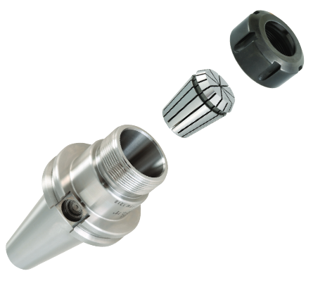
The Micrograd wrench allows you to set your collet clamping force so even the most fragile parts can be held safely and firmly according to Matt Saccomanno, CEO of Masa Tool. Cartridge and collet solutionIn 1996, Matt Saccomanno, CEO of Masa Tool, was frustrated with the limitations of conventional collets and workholding systems when performing secondary machining operations so his solution was to develop a high-precision, collet-type workholding device for small parts machining. The Microconic system consists of a cartridge and collet, with the cartridge fitting in the machine just like a standard legacy collet. The cartridge is a self-contained precision mechanism using the machine’s standard collet closing function, which means that the Microconic system can be used on any machine utilizing 5C, TF20, TF25 or TF37 collets. According to Saccomanno "Since a collet system for any given machine must be made large enough to fit the maximum workpiece diameter capacity of the machine, the result is the standard collet mechanism is designed to handle the largest workpieces, which means it is excessively forceful and bulky when used for the smaller workpieces. Smaller parts get sacrificed, because they typically require a higher degree of accuracy and the workholding is more critical." The Microconic system consists of the cartridge, which fits into your machine like a standard collet, and the Microconic collets which fit into Masa's unique cartridge. Every Microconic cartridge comes standard with extended nose for unsurpassed rigidity because of it's single piece construction. "In fact, the cartridge is so accurate that it can be used as a gauge to verify machine spindle accuracy," said Pakiz. Thayer explained how the Microconic system has worked for Micro-Matics "With the Masa system we're able to dial in a nice specific tension to hold that catheter part without crushing it or deforming it at all and having it on center. In a nutshell, we get better quality parts consistently with tighter tolerances. It's lead to a really significant improvement, it's increased throughput, so we have more parts at the end of the day." "As a result of the implementation, the scrap rate on this part dropped dramatically once we added the new Masa system by at least 30%." added Wobig. According to Masa Tool, the Microconic cartridge concentricity is guaranteed to be within 5µm (.0002") runnout and the collets are hardened and precision ground to the highest quality standards. The regular, UM10, 10mm collets, that Micro-Matics is using in their F20M10 Cartidge are available from Ø0.2mm (.008") to 10mm (.394"). In additon to the TF 20 spindles, the same collets can be used in TF25, TF37 and 5C sub spindles. Applying technology to other applications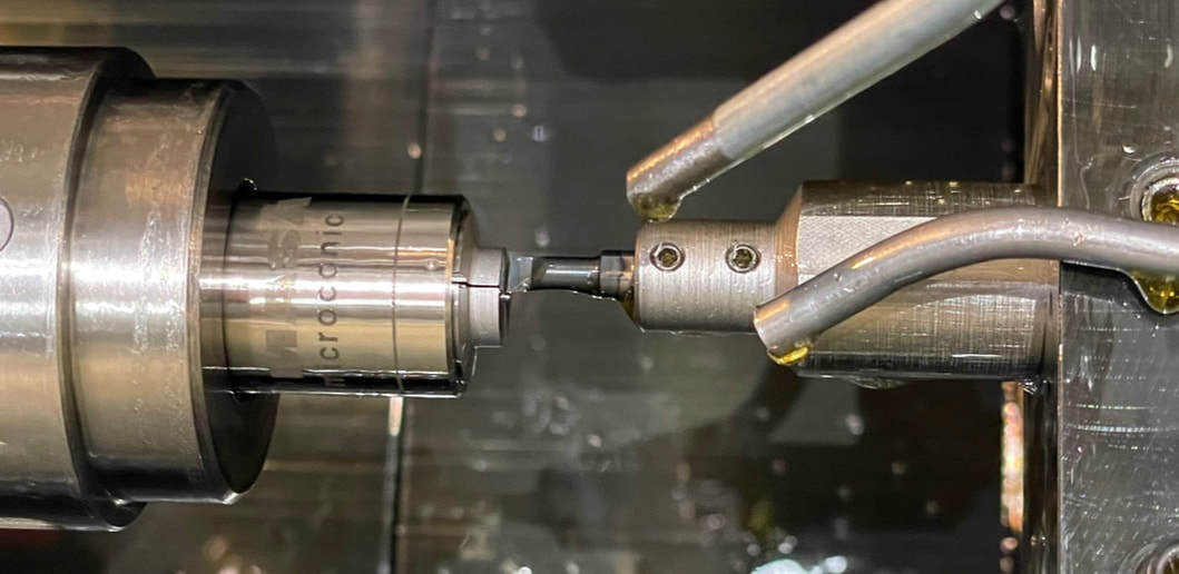 According to David Thayer at Micro-Matics, ""The extended nose pieces on the Microconic cartridge helps on the catheter tips because you can get closer up to where I actually have a supporting back end." Masa Tool's Microconic Cartidge is designed with an extended nose. Photo Courtesy Micro-Matics As time has gone on Masa's Microconic system has propagated to other machines and other jobs. Micro-Matics has been running one of the collets for a couple of months straight now on a distal coupler. Thayer explains, "The distal coupler part has a unique shape. It's not perfectly round. It has some small flats milled on either side of the part. It's like a cylindrical pill, like a capsule except with two sides of the long length milled in so there's flats on it. The part is 0.080" in length 0.040" in a cylindrical diameter. We then mill the cylindrical diameter 180 degrees from each other to a thickness of 0.030", so you're taking 0.10" off then drilling and centering two holes on each end of that through the flats." "Our customer is extremely concerned about any collet indication marks or chip marks on the outside of that cylindrical diameter. The previous collets we were using were custom made collets that actually had the profile of the part basically machined into it" says Wobig.
So what happened when they started using the Microconic system? "It fixed all that!" said Thayer. Remedying the issues"With the Microconic system, we didn't need to buy any special collets for any specific profile, we just got the actual diameter for the OD of the part and we're running it with that. The spaces in between on that collet is small enough that it's not distorting the round to flat portion if it even gets into there at all. So there's no timing issues at set-up. We just put it in there, set our tension, and start picking them off." added Wobig Thayer continued "The extended nose pieces on the Microconic cartridge helps on the catheter tips because you can get closer up to where I actually have a supporting back end. Because if I'm too far away from that supporting back and you have more of a tendency to crush the front of that part. The Microconic gives me a better tension on the part. On the distal coupler, we have to use a boring bar, or a facing tool to create the back face, which is round. We'd have a lot of trouble trying to hold without nibs or anything on there. And this holds it so that the part stays a little more square, and we're able to turn it better." When dealing with very small parts and setting with small gage pins, accidents do sometimes happen. "The only problem I've had with it was when somebody was trying to set the collet tension with a pin. They put the pin into the slot and not the hole and wrecked the collet. Because the pin was able to fit inside the slot so when they started tightening it up, and the pins started deforming the collet was wrecked because it wasn't in the hole in the center." said Thayer. Masa has indicated that they will release a new TF 15 and TF16 Cartridge with an entire series of smaller 5mm capacity collets at IMTS 2022. SpecificationsOver-grip 10mm collets from 0.5mm to 7.2mm diameter (0.020" to 0.283") open to 4mm (0.157") diameter larger than the clamping diameter. Some restrictions apply to larger sizes approaching the 7.2mm (0.283") max diameter.
Microconic over-grip collets have unmatched rigidity and concentricity compared to other manufacturers. The same collets can be used in TF20, TF25, and 5C sub spindles. Microconic collets permit interchangeability between machines, and the collets fit in any Microconic cartridge, no matter which collet system is in the machine.
0 Comments
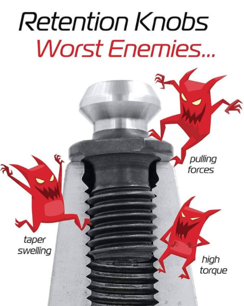
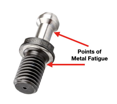
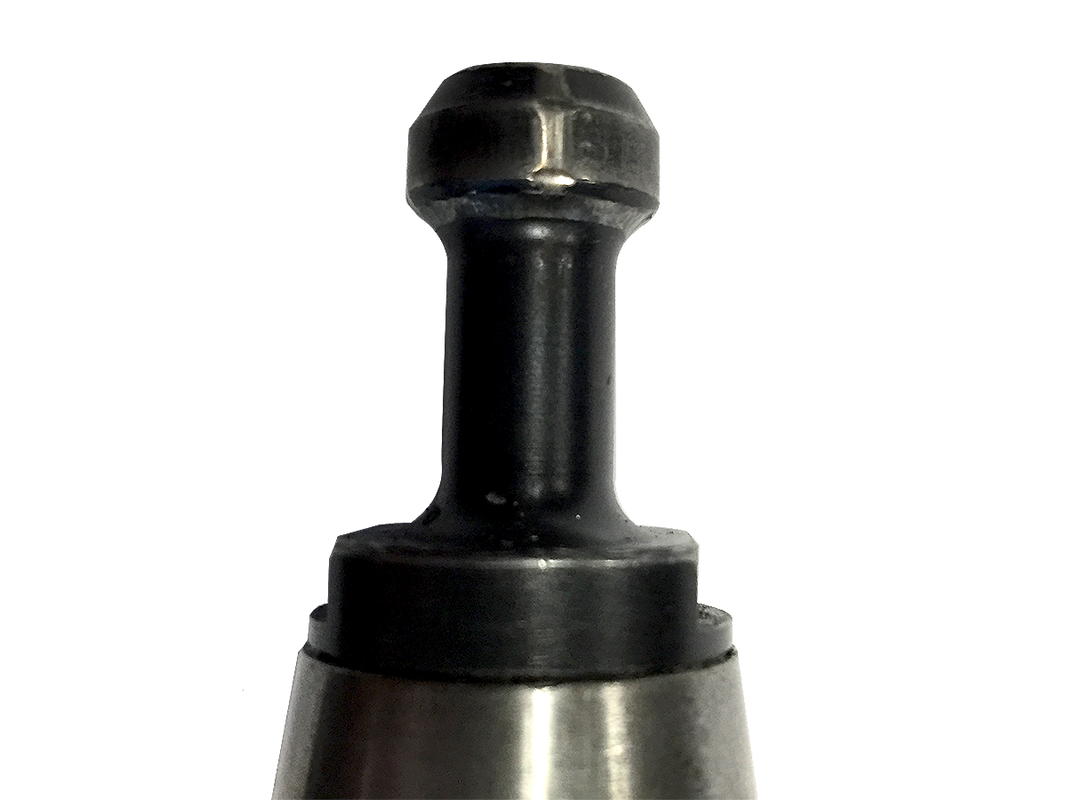
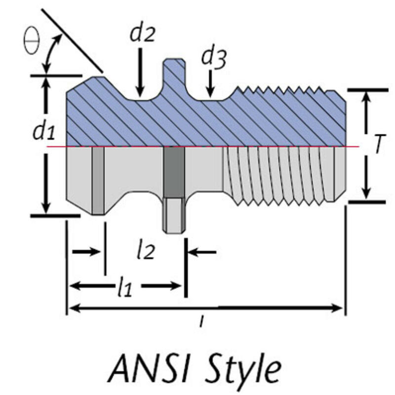
by Bernard Martin Retention Knobs are the critical connection between your machine tool and the tool holder and they are the only thing holding a steep taper tool holder in the machine’s spindle.
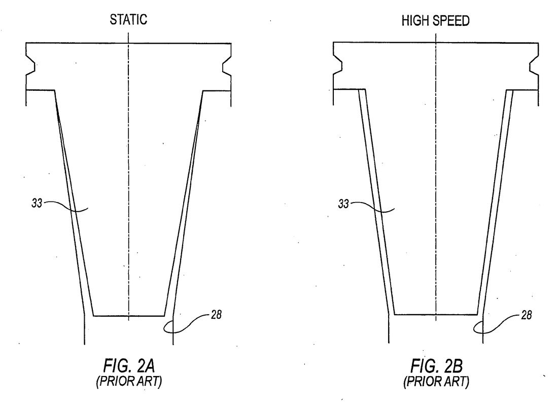
However, if you're running multiple shifts, 24-7, making lots of tool changes, making very heavy cuts with long reach or heavy cutting tools, and/or have ball lock style grippers instead of collet type grippers used on the retention knob, you will probably need to replace your studs at least every six months. Given the spindle speeds that we are running at to remain competitive, retention knobs are not an item that you want to take a chance on breaking. I can tell you firsthand that 5 pound toolholder with a drill in it flying out of the spindle at 23,000 RPM is not something you want to experience. Metal Fatigue: Why Pull Studs Fail
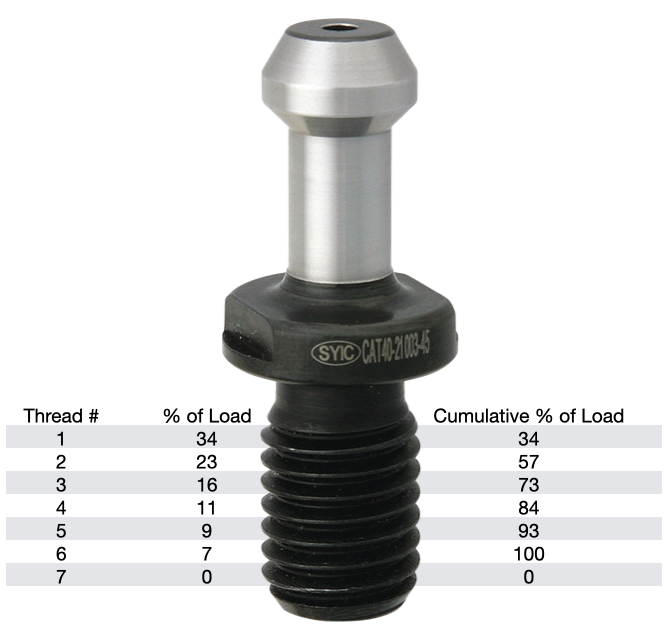
Additional threads beyond the sixth thread will not further distribute the load and will not make the connection any stronger. That is why the length of engagement of the thread on a pull stud is generally limited to approximately one to one & a half nominal diameter. After that, there is no appreciable increase in strength. Once the applied load has exceeded the first thread's capacity, it will fail and subsequently cause the remaining threads to fail in succession. Retention Knob DesignRepetitive cycles of loading and unloading subject the retention knob to stress that can cause fatigue and cracking at weak areas of the pull stud.
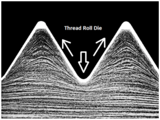
 Styles of MegaForce Retention Knobs MaterialNot all retention knobs are made from the same material, however, material alone does not make for a superior retention knob. Careful attention to design and manufacturing methods must be followed to avoid introducing potential areas of failure. Techniks MegaFORCE retention knobs are made from 8620H. AISI 8620 is a hardenable chromium, molybdenum, nickel low alloy steel often used for carburizing to develop a case-hardened part. This case-hardening will result in good wear characteristics. 8620 has high hardenability, no tempering brittleness, good weldability, little tendency to form a cold crack, good maintainability, and cold strain plasticity. There are some companies making retention knobs from 9310. The main difference is the lower carbon content in the 9310. 9310 has a tad more Chromium, while 8620 has a tad more nickel. Ultimate Tensile Strength (UTS) is the force at which a material will break. The UTS of 8620H is 650 Mpa (megapascals: a measure of force). The UTS of 9310H is 820 Mpa. So, 9310H does have a UTS that is 26% greater than 8620H. That said, Techniks chose 8620 as their material of choice because of the higher nickel content. Nickel tends to work harden more readily and age harden over time which brings the core hardness higher as the pull stud gets older. The work hardening property of 8620 makes it ideally suited for cold forming of threads on the MegaFORCE retention knobs. It should be noted that some companies are using H13. H13 shares 93% of their average alloy composition in common with 9310. 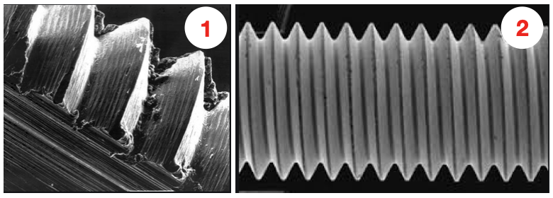 A cut thread, image 1, has a higher coefficient of friction due the the cutting process, while a roll formed thread, image 2, has a lower coefficient of friction which means that it engages deeper into the toolholder bore when subjected to the same torque. You will notice that Cutting threads tears at the material and creates small fractures that become points of weakness that can lead to failure. Rolled threads have burnished roots and crests that are smooth and absent of the fractures common in cut threads. Rolled Threads vs. Cut ThreadsRolled threads produce a radiused root and crest of the thread and exhibit between a 40% and 300% increase in tensile strength over a cut thread. The Techniks MegaFORCE retention knobs feature rolled threads that improve the strength of the knob by 40%.
MegaFORCE Geometric Design Features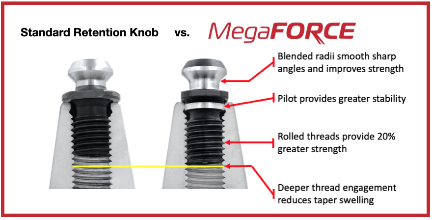 Features of Techniks MegaFORCE Retention Knobs Overall Length There are some claims that a longer projection engages threads deeper in the tool holder preventing taper swelling. While a deeper thread engagement can help prevent taper swelling, applying proper torque to the retention knob is an effective way to reduce taper swelling. An over-tightened retention knob may still cause taper swelling regardless of how deep it engages the threads of the tool holder. Additionally, the longer undercut section above the threads presents a weak point in the retention knob.
Retention Knob Best PracticesIn order to maximize the life of your retention knob and prevent catastrophic failure here are some technical tips to keep your shop productive and safe.
Indication Marks on Pull Studs is NOT Normal
Special thanks for Greg Webb at Techniks and Mike Roden from Fette Tools/ Turning Concepts, for providing technical insights.
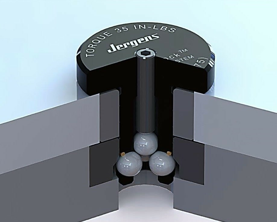
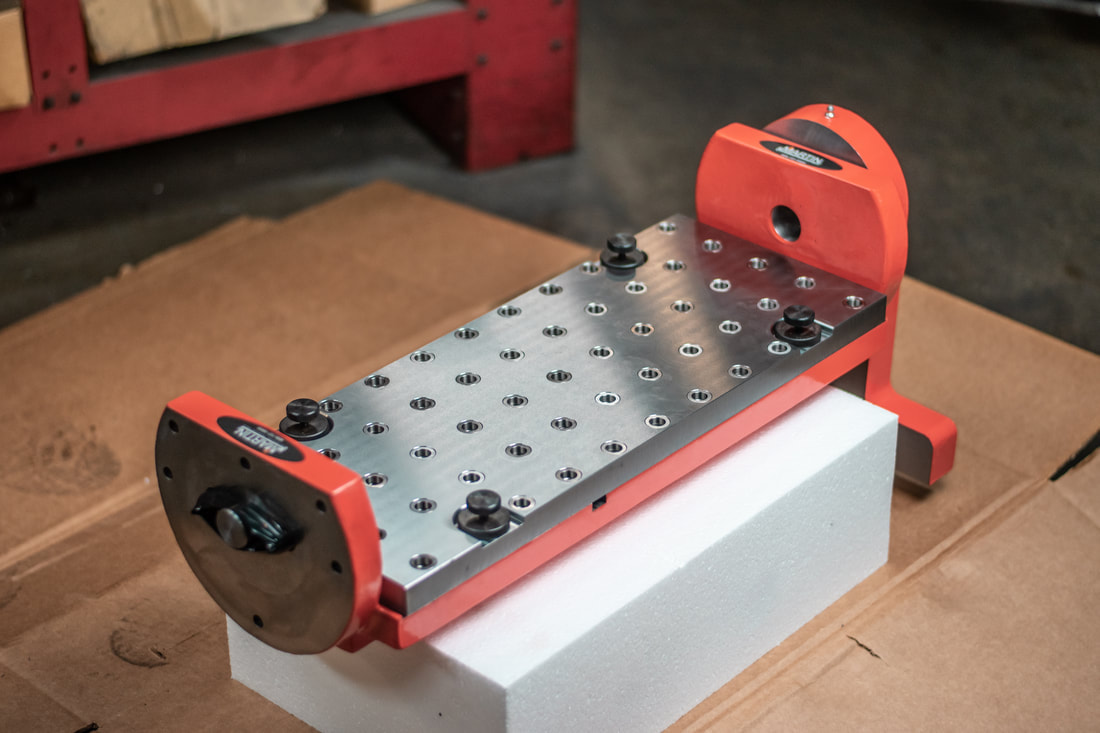 A custom workholding solution made by Martin Trunnion Tables utilizing Jergen Ball Locks for Timken This is a custom Stallion fixture with a 9/23 Quick Change made by Martin Trunnion Tables.
The product was made for Timken, a company out of British Columbia, Canada. Using Jergens Inc. Ball locks, the quick change option allows our customers to change setups quickly (within 60 seconds) and repeatably. The ball lock receiver bushing are mounted into 4 corners of the surface of the Stallion Trunnion Table. A 1" steel sub-plate, with hardened locater bushings in two of these corners, will act as the working surface. The sub-plate also includes a 2 inch grid pattern; this feature provides our customers with flexibility, as they are now able to mount virtually any vise or other workholding product onto their Stallion Trunnion Table. The trunnion is made from a one piece casting and is guaranteed flat and square within .001" over the entire surface.  Did you know that we now have a two 3D printers to help you develop custom tooling solutions? Some time ago we purchased a 3D Printer with a 8" x 8" x 7" Inches (200 x 200 x 180 mm) build area. We discovered it was great for making things for open houses and demo kits. But then we discovered that we could provide our customers with with tooling and workholding concepts so we upgraded and now make up to a maximum build volume of 1.38 cubic feet!! That;s a max build size of 14” x 14” x 12.4” (355 x 355 x 315mm)! We are started out using our 3D printers to produce working parts for customer applications as well as trade show tool display stands. Now we are using these both our Wanhao Duplicator 6 Plus and our new Fusion 3D F410 printers to help our customers with visualization and verification of workholding ideas, tool holding clearances as well as many other applications. If you're interested in working on some ideas with us, just fill out the 3D Printing Request Form
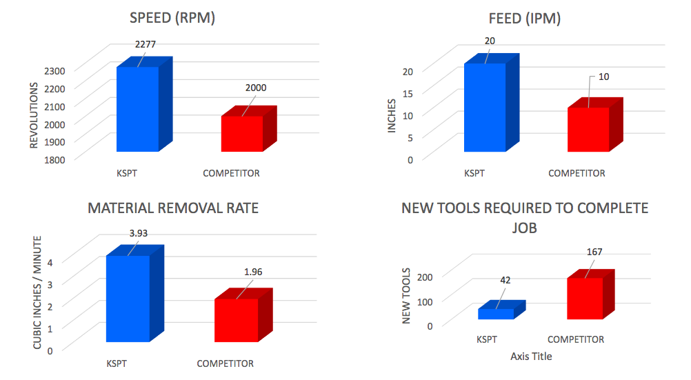
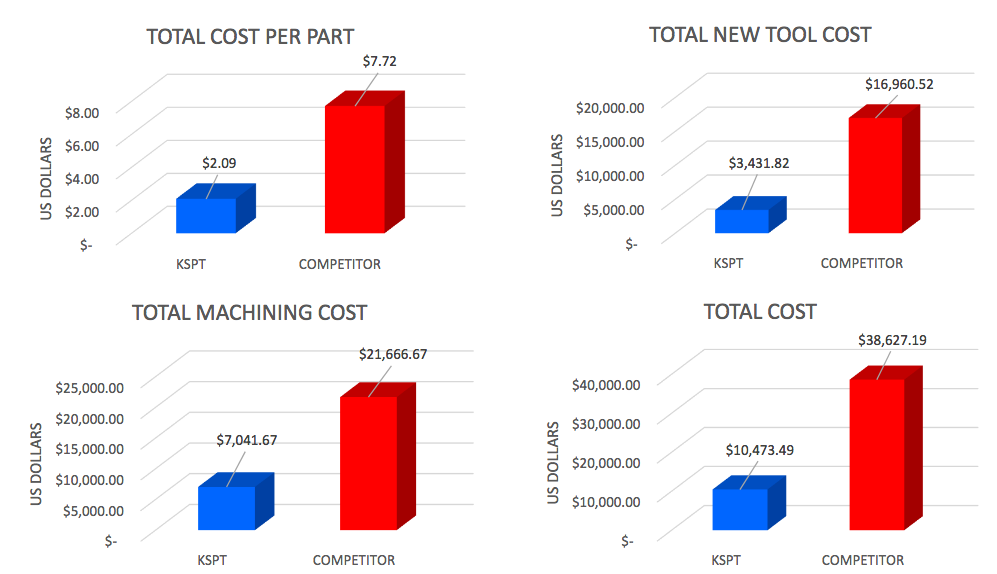
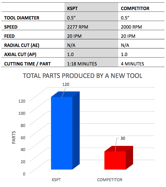
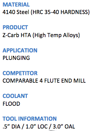
GOALS The goals of this study were to significantly reduce job cost through increasing tool life and maximizing operating efficiencies
  Forming taps displace metal — cutting taps remove it. 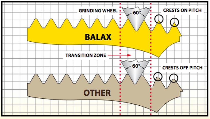 BALAX stands for “BALanced AXially,” which is an important feature for all of our Thredfloer Cold Forming Taps. Balax Thredfloers are ground using our proprietary thread grinders that have a differential lead compensation device that produces cold forming taps with their lead crests exactly on pitch. Other forming taps have lead thread cold forming teeth that are not ground on pitch. These forming taps actually cold-work the thread twice:
Balax Thredfloers form the thread exactly on pitch the first time with no axial thrust, hence the name “BALanced AXially”. All Thredfloers require less tapping torque and provide longer tap life than forming taps ground with conventional methods. 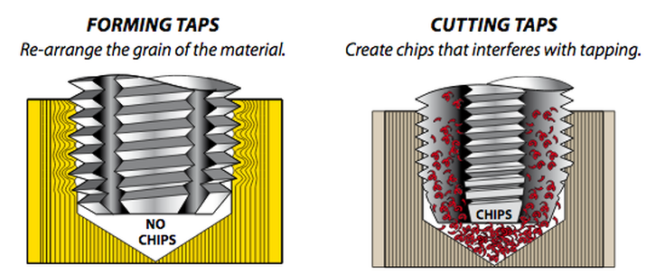 Forming taps and cutting taps produce threads that gage identically and are interchangeable, but the similarity stops there. The way they produce threads is completely different:
Although Ball-Lock® is a simple, robust, quick-change system some simple maintenance can keep is performing at its best and add life to the components. Did you know regularly cleaning chips and debris from your receiver bushings is recommended? It can significantly extent the life of your quick-change system.
To sum it up regularly cleaning chips and debris from your bushings is recommended. If you notice any signs of wear we recommend replacing the damaged parts with one of our shank repair kits. These kits include a new set of balls, o-ring and a set screw. Click here to learn more. Happy Machining and make chips happen!
We would like to introduce a NEW employee to the High Tech Family! Jason Hoppe joined us at the beginning of the November. Jason comes to us with a 10+ year machine shop experience, as well as 4+ years working in Industrial Distribution with BlackHawk. Jason Hoppe started with High Tech Industrial Representation to increase and support the sales growth of the manufacturing they work with. Prior to joining High Tech, Jason worked at BlackHawk Industrial as an Account Manager. While at BlackHawk Jason managed a sales territory in Central, MN. He negotiated contracts and worked on machine processes to increase productivity. He also worked with customers to help manage their level of inventory in their vending solutions and also with BlackHawk’s warehouses. He would also help with new projects to select the proper work holding and tooling selection. He worked on many tooling packages for new machines. He also ran cost saving solutions to justify cost on the projects. Before working at BlackHawk, Jason worked at a machine shop in Melrose, MN. He started as a machine operator on nights. After a month of working nights they saw his potential and moved him up to days as a set-up machinist. Working in that role for 3 years they gave him the opportunity to become the shop programmer. While working as the shop programmer things progressed quickly and that lead to a supervisor role. He was then in charge of workers on a day and night shift schedule. Jason is also a Volunteer Firefighter for the Freeport Fire Department. He joined the Fire Department Jan 1 of 2007. He is a certified First Responder and Firefighter. While being on the department he was elected to take on the responsibility of 2nd Assistant Chief and was in that role for 2 years. He has fought many structure fires in and around his community. He has also responded to many medical and car accidents. Jason lives in the country around the Melrose area with his wife, Heidi, and their children, Thor, Sawyer, and Tucker. He enjoys spending time with his family, camping, going golfing, hunting and fishing. Please help me welcome him! Minneapolis and North Minnesota. Jason Hoppe [email protected] 888.654.5380 x102 Cell; 320.250.1088  University engineering students will show off racecar assemblies produced with cutting tools from Kyocera SGS Precision Tools. 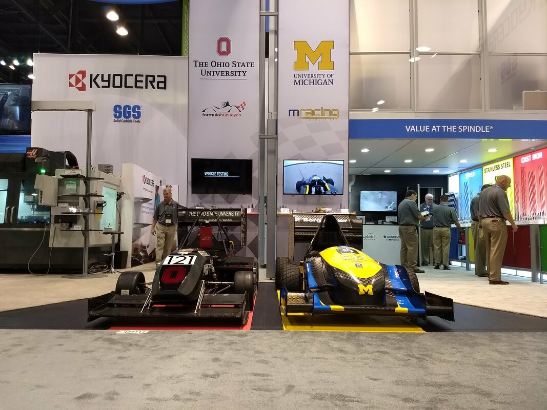 Engineering students from the University of Michigan and The Ohio State University show off Formula SAE assemblies at Kyocera SGS Precision Tools’ IMTS booth 432217. One of college athletics’ biggest rivalries—Buckeyes vs. Wolverines—is on full display this year in the West Building, at the Kyocera SGS Precision Tools’ IMTS booth 432217. The sport isn’t football, but racing, with teams of engineering students from the Ohio State University and the University of Michigan showing off their own designs for Formula SAE race cars. The result of months of engineering and hands-on learning, the fabricated assemblies share one aspect in common: the manufacturing process employed cutting tools from Kyocera SGS Precision Tools (KSPT). Attendees to KSPT’s booth are invited to see the projects and meet the student teams in addition to browsing the company’s wide selection of tools, which it donates to various schools’ mechanical engineering programs for assorted projects. The Ohio State University’s Formula Buckeyes motorsport program challenges students of all majors, backgrounds, skill levels and degrees of experience to compete in one of six student teams. Students apply research and classroom concepts as well as learn hands-on skills for designing, fabricating, racing, managing and marketing competition vehicles. This experience includes machining, engine testing, battery testing, computer-aided design and many other engineering tools. The University of Michigan’s M racing Formula SAE Collegiate motorsport racing series challenges students’ technical innovation and advanced engineering analysis abilities to build formula-style race cars. Fifteen global competitions test each team’s dynamic design theory, budgeting and marketing. The program provides students with a competitive career advantage in the industry and exposes them to different cultures and approaches to engineering. There are over 500+ teams ranked on their performance in six competitions via a point system striving for #1 ranking in the world. Editors Note: The original article in Modern Machine Shop was entitled, " " and made reference to "Formula 1" within the article. It has been corrected in this re-post of the original article to reference "Formula SAE"
General Overview Modern CNC machines feature high-capacity tool changers that automatically swap toolholders in and out of the spindle as needed, by means of a high speed swing arm or a rotary carousel.
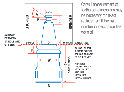
Sizing Toolholders
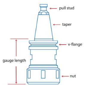
Parts of Toolholder
Pull Studs / Retention Knob
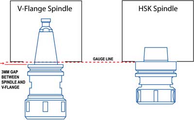
Taper
V- Flange
Collet Pocket  The last part of the toolholder is the collet pocket, into which the collet is inserted before being secured by various types of collet nuts. The collet pocket, internal 8 degree taper, should hold the same tolerance as the taper as they work together to control runout
|
News & Applications
Learn about the latest breaking news and applications that we're working on right here! Archives
June 2022
Categories
All
|

 RSS Feed